This tab lets you define the drawing views ADC creates, separately for each document type. Each type keeps its own views, styles, scales, sheet sizing, and section settings — so assemblies, standard parts, and sheet-metal parts can each get a completely different drawing layout.
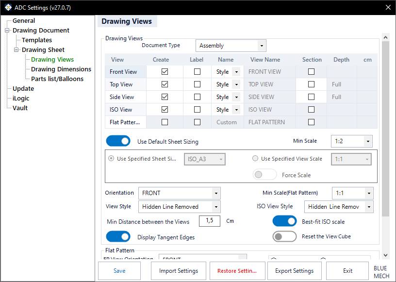
Document Type
Pick the document type you want to edit — Assembly, Standard Part, or Sheet Metal. Every setting on this tab applies to the type selected here, so you can set each one up independently.
Drawing Views grid
The grid lists the available views — Front, Top, Side, Iso, and Flat Pattern — for the selected document type. For each view you can choose whether to create it (Create), whether to show its label (Label), and how its name is set (Name: from the style, or a Custom name typed in the View Name column). Leave at least one active view per document type. The Flat Pattern row is available for sheet-metal parts.
The Top and Side views can be created as section views. Where a section is used, set its Depth to Full (through the whole model) or to a custom value in centimetres.
View Style
Sets the style of the standard (front, top, side) views for the selected document type: Hidden Line, Hidden Line Removed, or Shaded.
ISO View Style
Sets the style of the ISO view for the selected document type, separately from the standard views: Hidden Line Removed or Shaded.
Orientation
Sets the front-view orientation used for the selected document type (Front, Back, Right, Left, Top, or Bottom). Choose Allow me to choose to pick the orientation interactively when the drawing is created.
Use Default Sheet Sizing
- Activated: ADC automatically chooses the sheet size and view scale for the selected document type, scaling the views down only as far as the Min Scale below. This is the simplest mode and is the default for assemblies and standard parts.
- Deactivated: the options below become available so you can pin an exact sheet size or an exact view scale.
Min Scale
The smallest scale ADC will shrink the views to when fitting them automatically, so drawings are not scaled down onto an unreasonably small sheet.
Use Specified Sheet Size
Pins the drawing to one exact sheet size for the selected document type (for example ISO A3); ADC uses that sheet and will not grow to a larger one. Sheet-metal drawings use a specified A3 sheet by default.
Use Specified View Scale
Pins the views to one exact scale instead of a fixed sheet size, and lets the sheet size follow from that scale.
Force Scale
- Activated: keeps your chosen view scale even when the views are too big to fit, instead of scaling them down automatically — use this when the scale matters more than fitting everything on one sheet. Applies when a specified view scale is in use.
Best-fit ISO scale
- Activated: ADC may scale the ISO view to a non-standard scale so it best fills its area on the sheet.
- Deactivated: the ISO view uses a standard scale.
Min Distance between the Views
Sets the minimum spacing ADC keeps between the placed views.
Display Tangent Edges
- Activated: tangent edges are shown in the views.
- Deactivated: tangent edges are hidden.
Reset the View Cube
- Activated: ADC resets the ViewCube before capturing the model orientation, for predictable view directions.
Flat Pattern
For sheet-metal parts, these options control the flat-pattern view. Use Recommended Flat Pattern View Position lets ADC find the best position; otherwise you set the side with FP Left or FP Right. FP View Orientation sets the flat-pattern orientation, and CW Rotation / CCW Rotation set the rotation direction. Match Front View and FP Scales forces the flat-pattern scale to match the front view, and Min Scale (FP) sets the minimum flat-pattern scale.