The Flat DXF layers tab controls the flat-pattern DXF written for sheet-metal parts. It does not affect DXF files exported from drawings — those go through the drawing DXF translator and keep their own settings.
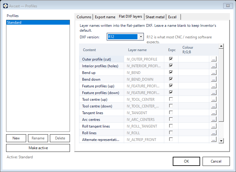
DXF version
Sets the AutoCAD version the DXF is written for. R12 is the default, because it is the version most cutting and nesting software accepts without complaint.
The layer table
The table lists the kinds of geometry a flat pattern can contain, and for each one you can set the layer name it is written to, whether it is exported at all, and its colour, line type and line weight:
- Outer profile and interior profiles
- Bend up and bend down lines
- Feature profiles
- Tool centres
- Tangent lines
- Arc centres
- Roll lines
- Alternate representation
Line type and line weight are shown as drawn samples rather than named, in the layer’s own colour, so you pick the pattern you can see rather than telling “long dash triple dotted” apart from “double dash triple dotted” by reading. Line weight is set in millimetres.
One thing to know before you set weights: a line weight is written into a DXF field that only exists from AutoCAD 2000 onwards. At R12 — the default above — there is nowhere in the file to put it, so choose a newer DXF version if your machine or nesting package reads line weights.
The usual reason to change these is a cutting machine or nesting package that expects particular layer names, or one that should only receive the outer profile and nothing else.
Check the first DXF you produce against your machine’s expectations before running a large batch through it.